CT-Natural
Windows Application (64-bit)

CT-Natural
$9989
- One (1) Installation License
- For Commercial Use
- One-Year Email Support
- Free Minor Upgrades
Requirements
-
•
Windows Versions (64-bit): Windows 11, Windows 10
-
•
Application is available only in 64-bit version.
Downloads
CT-Natural (User Guide)CT-Natural
Version 2.0
Computational software to analyze and determine cooling performance curves and thermophysical operational variables in natural draft counterflow wet cooling towers.
All calculations are performed employing accurate numerical techniques implementing some of the most precise mathematical models for the properties of humid air, water and steam developed for industrial purposes.
Natural Draft Counterflow Cooling Towers.
Demand Curves.
Merkel Number.
Psychrometrics Calculator.
Natural Draft
Numerical calculation and graphical display of operational variables in natural draft counterflow cooling towers based on a mathematical model of heat and mass transfer between water film and humid air in the cooling fill.
Graphical and numerical calculation of operational variables in natural draft counterflow cooling towers based on a mathematical model of heat and mass transfer between water film in the cooling fill and humid air.
Complete validation of input variables, informing the user of the correct range of variables for a valid data calculation.
Creation of projects in a database that describe a particular set of atmospheric and operational conditions together with tower characteristics, and data calculation results for later retrieval or recalculation.
Generation of high-quality pdf files of temperature curve plots and data calculation points for a particular project.
Generation of excel and pdf files of numerical results of data calculations.
Supports input variables and calculation results in SI (metric) and I-P (English) system of units.
Demand Curves
Calculation and graphical display of demand curves and approach data points.
Calculation and graphical display of demand curves following the integration of Merkel´s equation.
Calculation and graphical display of approach data points.
Complete validation of input variables.
Creation of projects in a database that describe a particular set of input variables together with the calculated demand curves and approach data points for later retrieval or recalculation.
Generation of high-quality pdf files of demand curve plots.
Generation of excel and pdf files of approach data point calculations results.
Supports input variables and calculation results in SI (metric) and I-P (English) system of units.
Merkel Number
Calculation of Merkel number using the Chebyshev numerical method.
Calculation of Merkel number using the Chebyshev numerical method.
Complete validation of input variables, informing of the correct range of variables for a valid calculation.
Supports input variables and calculation results in SI (metric) and I-P (English) system of units.
Psychrometrics Calculator
A psychrometrics calculator based on the latest mathematical models to numerically evaluate the properties of humid air, water, steam and ice.
Calculation of 42 properties of humid air, water, steam, ice and psychrometrics.
It allows for 17 combinations of two thermodynamic properties to be entered as input parameters.
Complete validation of input thermodynamic properties, it calculates and provides the user with information about the appropriate input values in the valid range of computations.
Supports input variables and calculation results in SI (metric) and I-P (English) system of units.
Introduction
A natural draft counterflow wet cooling tower (NDCWCT) is a device that utilizes the effects of mass and energy transfer to cool water by providing cold air flows “through”a hot water flow. The heat rejected to the atmosphere is in the form of latent and sensible heat and is carried away by the air flow through the tower. The water is cooled first by breaking it up into droplets (or spray), and then by making it flow in the form of thin films inside the cooling fill, allowing it to come into contact with the air which eventually carries the heat away into the atmosphere.
Considering that most of the heat and mass transfer ocurrs in the cooling fill for this type of cooling tower, the numerical calculations performed in Natural Draft (version 2.0) are focused only in the cooling fill zone. Figure 1 shows an schematic of a NDCWCT and some of the input variables required for the computations of the thermophysical variables and cooling performance.
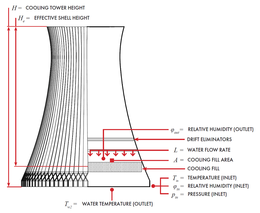
Schematic of a NDCWCT and some of the input variables in Natural Draft.
An energy formulation that incorporates the heat and mass transfer process between water and humid air in the cooling fill is numerically solved to calculate isotherms of the outlet water temperature given a set of atmospheric and operating conditions in a NDCWCT.
Some of the assumptions and simplifications considered in the energy model used in Natural Draft are summarized as follows:
Calculations of heat and mass transfer are conducted in the cooling fill zone.
Operation of the cooling tower is under steady-state conditions, without considering wind effects.
Water and air flow rates are uniform over the cross sections of the cooling tower.
Humid air is saturated when leaving the cooling fill, i.e., Relative Humidity (Outlet) = 100%.
For the calculation of the thermophysical properties of water, steam and humid air used in the numerical solution of the energy model used in Natural Draft, the following formulations of properties are implemented:
Properties of Water and Steam
Formulations from the IAPWS (International Association for the Properties of Water and Steam) IAPWS-IF97 Industrial formulation (Revision 2007) and related models.
Properties of Humid Air
Thermodynamic and psychrometric property algorithms from the ASHRAE Research Project 1485.
Scientific Formulation IAPWS-95, IAPWS Formulation 2008 and IAPWS Formulation 2006. Properties of dry air are from the NIST Reference equation of Lemmon et al.
Graphical User Interface
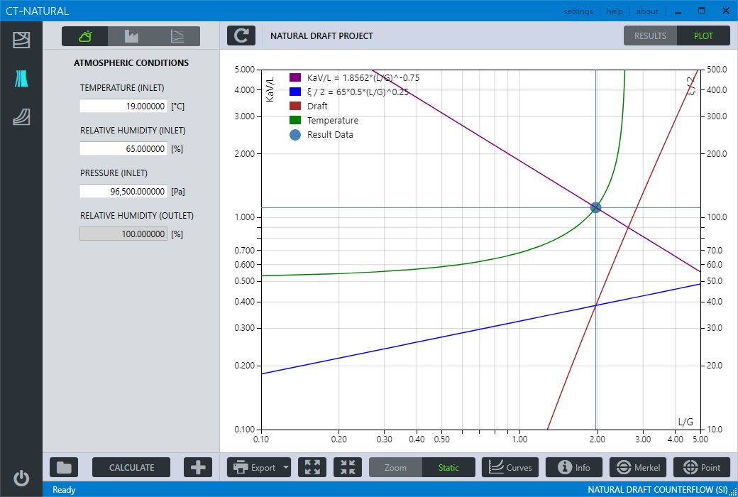
Graphical User Interface in Natural Draft.
| Input Variable | Definition |
|---|---|
| TEMPERATURE (INLET) | Temperature of dry-bulb air entering the cooling tower. |
| RELATIVE HUMIDITY (INLET) | Relative humidity of air entering the cooling tower. |
| PRESSURE (INLET) | Total pressure referred to atmospheric, at the entrance of the cooling tower. |
| RELATIVE HUMIDITY (OUTLET) | Relative humidity of air leaving the cooling fill. |
| EFFECTIVE SHELL HEIGHT | Normally taken as height from middle of packing to top of tower shell. |
| COOLING FILL AREA | Total packing area normal to air flow. |
| WATER FLOW RATE | Mass water flow entering into the cooling tower. |
| WATER LOADING | Mass water flow per unit plain area of packing (calculated). |
| COOLING RANGE | Difference between hot water temperature and cold water temperature. |
| WATER TEMPERATURE (OUTLET) | Estimated average temperature of the cold water basin discharge (outlet). |
| HEAT TRANSFER ADJUSTMENT | Adjustment factor for the heat transfer process in the cooling fill. |
| COEFFICIENT C | Constant defined for a particular packing design. |
| EXPONENT N | Exponent defined for a particular packing design. |
| COEFFICIENT R | Constant for resistance curve characteristic for a particular cooling tower. |
| EXPONENT M | Exponent for resistance curve characteristic of a particular cooling tower. |
Definition of input variables in Natural Draft.
Range of Input Variables
| Property | Range in SI Units | SI Units |
|---|---|---|
| TEMPERATURE (INLET) | -20.0 ≤ T ≤ 60.0 | °C |
| RELATIVE HUMIDITY (INLET) | 0.0 ≤ R.H. ≤ 100.0 | % |
| PRESSURE (INLET) | 60000.0 ≤ P ≤ 110000.0 | Pa |
| RELATIVE HUMIDITY (OUTLET) | R.H. = 100.0 | % |
| EFFECTIVE SHELL HEIGHT | 10.0 ≤ Height ≤ 300.0 | m |
| COOLING FILL AREA | 19.64 ≤ Area ≤ 31415.92 | m2 |
| HEAT TRANSFER ADJUSTMENT | -1.0 ≤ Factor ≤ 1.0 | 1 |
| WATER FLOW RATE | 0.5 ≤ Flow ≤ 100000.0 | kg/s |
| COOLING RANGE | 1.0 ≤ T ≤ 50.0 | °C |
| WATER TEMPERATURE (OUTLET) | 1.0 ≤ T ≤ 70.0 | °C |
| COEFFICIENT C | 1.0 ≤ C ≤ 3.0 | 1 |
| EXPONENT N | -2.0 ≤ N ≤ -0.1 | 1 |
| COEFFICIENT R | 20.0 ≤ R ≤ 500.0 | 1 |
| EXPONENT M | -4.0 ≤ M ≤ 4.0 | 1 |
| KaV/L | 0.1 ≤ KaV/L ≤ 5.0 | 1 |
| L/G | 0.1 ≤ L/G ≤ 5.0 | 1 |
| PERFORMANCE CURVE | 1.0 ≤ T ≤ 60.0 | °C |
Full range of input variables for Natural Draft in SI Units.
Calculation Results
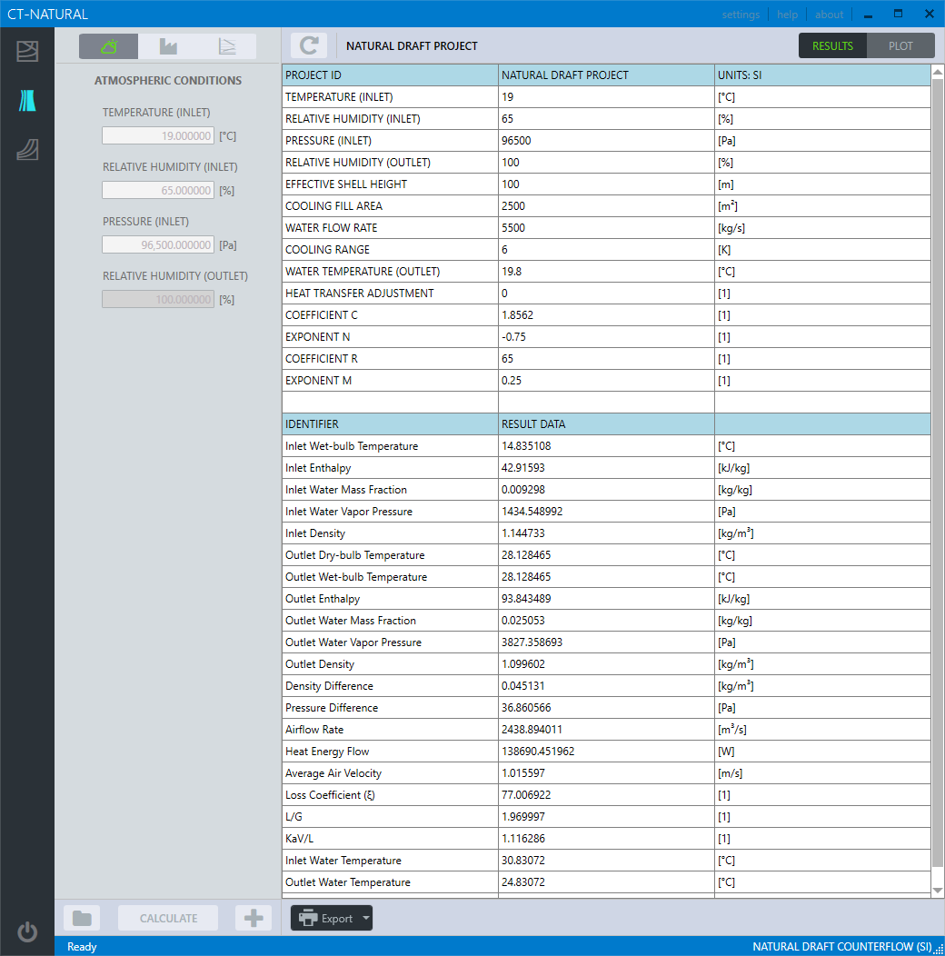
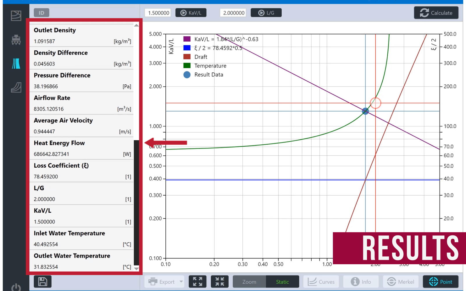
Numerical Results in a calculation project in Natural Draft.
| Result Variable | Definition |
|---|---|
| Inlet Wet-bulb Temperature | Wet-bulb temperature of air entering the cooling tower. |
| Inlet Enthalpy | Specific enthalpy of air entering the cooling tower. |
| Inlet Water Mass Faction | Water mass fraction at the entrance of the cooling tower. |
| Inlet Water Vapor Pressure | Water vapor pressure at the entrance of the cooling tower. |
| Inlet Density | Specific density of air entering the cooling tower. |
| Outlet Dry-bulb Temperature | Dry-bulb temperature of air leaving the cooling fill inside the cooling tower. |
| Outlet Wet-bulb Temperature | Wet-bulb temperature of air leaving the cooling fill inside the cooling tower. |
| Outlet Enthalpy | Specific enthalpy of air leaving the cooling fill inside the cooling tower. |
| Outlet Water Mass Faction | Water mass fraction leaving the cooling fill inside the cooling tower. |
| Outlet Water Vapor Pressure | Water vapor pressure leaving the cooling fill inside the cooling tower. |
| Outlet Density | Specific density of air leaving the cooling fill inside the cooling tower. |
| Density Difference | Density difference of air at the entrance of the cooling tower and air leaving the cooling fill. |
| Pressure Difference | Pressure difference at the entrance of the cooling tower and leaving the cooling fill. |
| Airflow Rate | Airflow rate leaving the cooling fill. |
| Heat Energy Flow | Total amount of heat energy transferred from the cooling tower. |
| Average Air Velocity | Average air velocity of humid air in the cooling fill. |
| Loss Coefficient | Non-dimensional coefficient referred to the pressure loss in the cooling fill. |
| L/G | Calculated ratio of water flow rate to airflow rate |
| KaV/L | Calculated tower characteristic (Merkel number). |
| Inlet Water Temperature | Calculated inlet water temperature. |
| Outlet Water Temperature | Calculated outlet water temperature. |
Table 3.
Definition of calculation result variables in Natural Draft.
Merkel Number
Introduction
An evaporative cooling tower is a device that is used to remove waste heat from the water used in an industrial process equipment or a machinery by rejecting that waste heat into the environment. When water is mixed with air in a cooling tower configuration, a heat transfer process takes places that involves a latent heat transfer due to the vaporization of a small amount of water and a sensible heat transfer reflecting the difference in temperatures of water and air.
Based on the theory developed by Merkel, the heat transfer process that occurs in a cooling tower by considering the enthalpy potential difference as the driving force is described by the Merkel equation:
where
| $\frac{{KaV}}{L} $ | $=$ | Tower characteristic | |
| $T{}_1 $ | $=$ | Hot water temperature (inlet) | |
| $T{}_2 $ | $=$ | Cold water temperature (outlet) | |
| $h' $ | $=$ | Enthalpy of saturated air at water temperature | |
| $h $ | $=$ | Enthalpy of main airstream | |
| ${c_{pw}}$ | $=$ | Specific heat capacity of water | |
| $d{T_w}$ | $=$ | Temperature differential of water |
The Merkel Number application solves the equation (1) numerically using the four-point Chebyshev numerical method employing the following models for the calculation of water and air properties:
Properties of Water and Steam
Formulations from the IAPWS (International Association for the Properties of Water and Steam) IAPWS-IF97 Industrial formulation (Revision 2007) and related models.
Properties of Humid Air
Thermodynamic and psychrometric property algorithms from the ASHRAE Research Project 1485.
Scientific Formulation IAPWS-95, IAPWS Formulation 2008 and IAPWS Formulation 2006. Properties of dry air are from the NIST Reference equation of Lemmon et al.
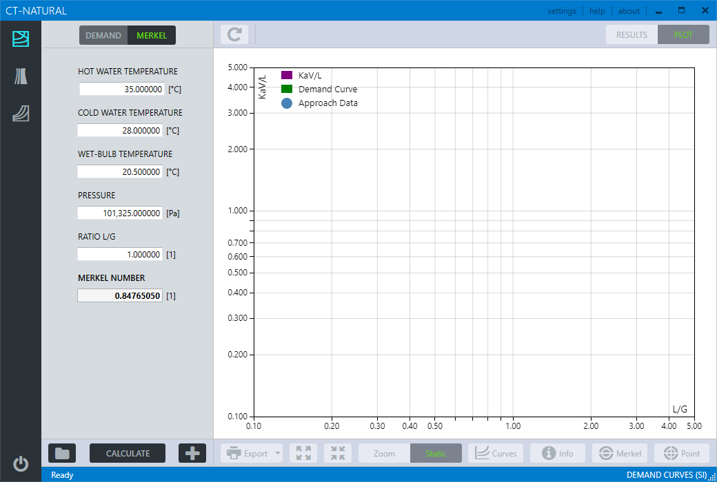
Graphical User Interface
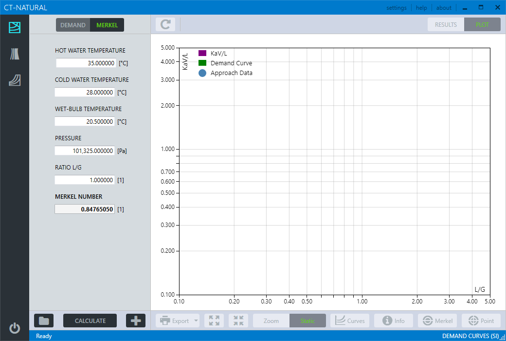
Merkel Number calculation in CT-Natural.
Range of Input Variables
| Property | Range in SI Units | SI Units |
|---|---|---|
| HOT WATER TEMPERATURE | 1.0 ≤ T ≤ 90.0 | °C |
| COLD WATER TEMPERATURE | 1.0 ≤ T ≤ 90.0 | °C |
| WET-BULB TEMPERATURE | 1.0 ≤ T ≤ 90.0 | °C |
| PRESSURE | 60000 ≤ P ≤ 110000 | Pa |
| RATIO L/G | 0.01 ≤ L/G ≤ 5.0 | 1 |
| Property | Range in I-P Units | I-P Units |
|---|---|---|
| HOT WATER TEMPERATURE | 33.8 ≤ T ≤ 194.0 | °F |
| COLD WATER TEMPERATURE | 33.8 ≤ T ≤ 194.0 | °F |
| WET-BULB TEMPERATURE | 33.8 ≤ T ≤ 194.0 | °F |
| PRESSURE | 8.70226426 ≤ P ≤ 15.95415115 | psia |
| RATIO L/G | 0.01 ≤ L/G ≤ 5.0 | 1 |
Demand Curves
Introduction
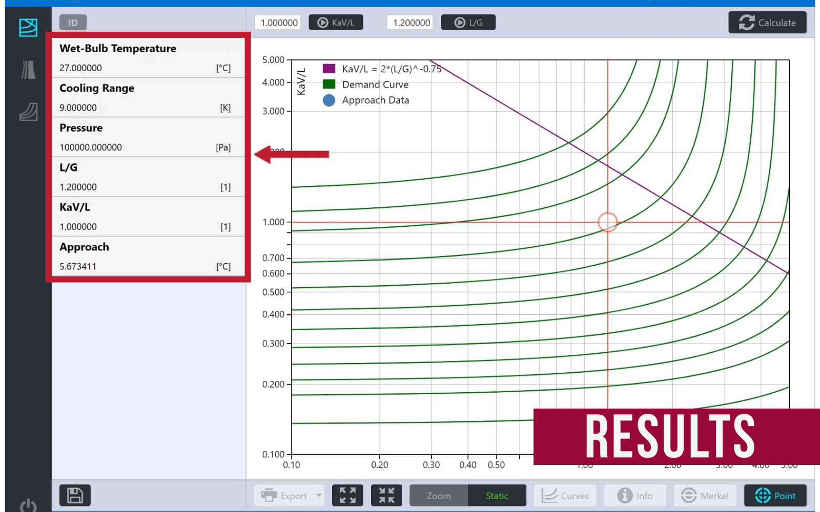
Demand Curves allows to calculate and plot in a log-log graph isolines resulting from the integration of equation (1) using as a parameter an approach value. It also calculates the approach given a pair of values determined by KaV/L and L/G, both in the SI and I-P system of units. The definition of the input variables for calculation of the demand curves is given in Table X.
For a specific tower, there is a characteristic curve in the form of a plot of tower characteristic, $KaV/L$, versus water to air flow ratio, $L/G$. This plot is described with an equation of the following form:
Graphical User Interface
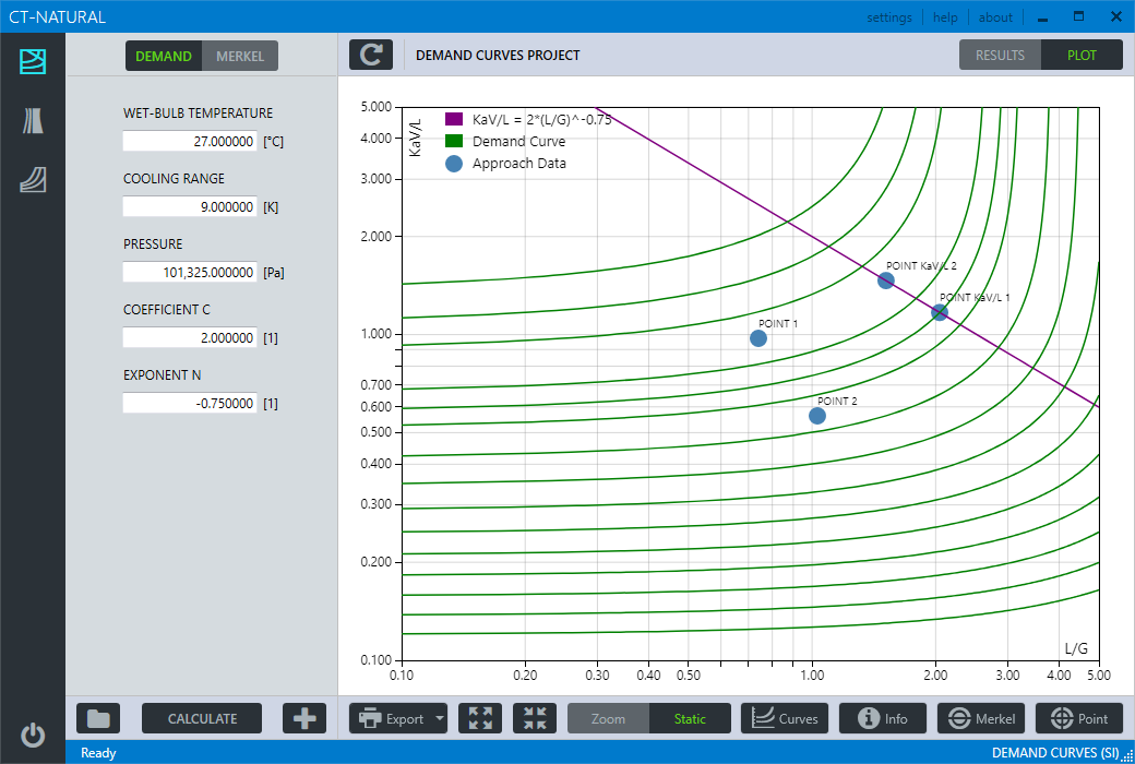
| Input Variable | Definition |
|---|---|
| WET-BULB TEMPERATURE | Temperature of air wet-bulb entering the cooling tower |
| COOLING RANGE | Difference between hot water temperature and cold water temperature |
| PRESSURE | Total pressure referred to atmospheric |
| COEFFICIENT C | Constant defined for a particular packing design |
| EXPONENT N | Exponent defined for a particular packing design |
Range of Input Variables
| Property | Range in SI Units | SI Units |
|---|---|---|
| WET-BULB TEMPERATURE | 1.0 ≤ T ≤ 90.0 | °C |
| COOLING RANGE | 0.1 ≤ T ≤ 90.0 | °C |
| PRESSURE | 60000 ≤ P ≤ 110000 | Pa |
| COEFFICIENT C | 1.0 ≤ C ≤ 3.0 | 1 |
| EXPONENT N | -2.0 ≤ N ≤ -0.1 | 1 |
| KaV/L | 0.1 ≤ KaV/L ≤ 5.0 | 1 |
| L/G | 0.1 ≤ L/G ≤ 5.0 | 1 |
| Approach | 1.0 ≤ T ≤ 60.0 | °C |
| Property | Range in I-P Units | SI Units |
|---|---|---|
| WET-BULB TEMPERATURE | 33.8 ≤ T ≤ 194.0 | °F |
| COOLING RANGE | 0.1 ≤ T ≤ 162.0 | °F |
| PRESSURE | 8.70226426 ≤ P ≤ 15.95415115 | psia |
| COEFFICIENT C | 1.0 ≤ C ≤ 3.0 | 1 |
| EXPONENT N | -2.0 ≤ N ≤ -0.1 | 1 |
| KaV/L | 0.1 ≤ KaV/L ≤ 5.0 | 1 |
| L/G | 0.1 ≤ L/G ≤ 5.0 | 1 |
| Approach | 1.0 ≤ T ≤ 140.0 | °F |
Calculation Results
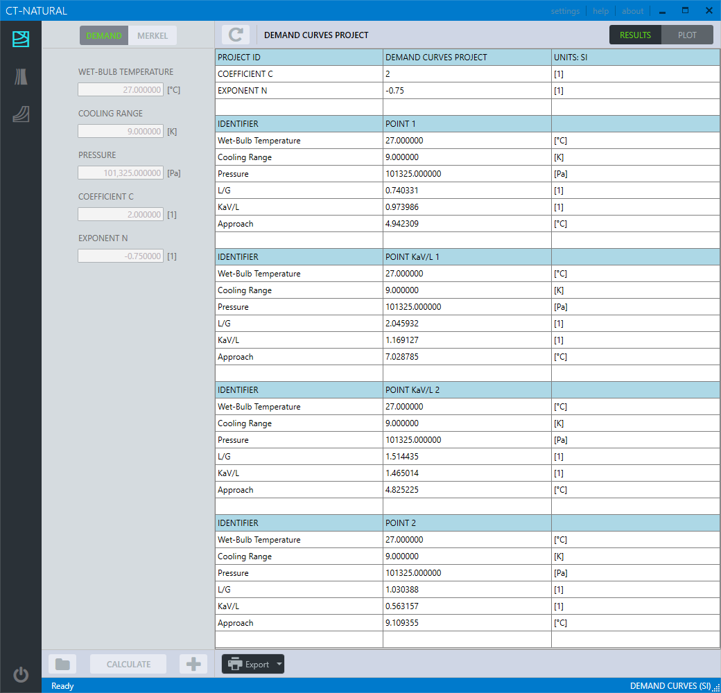
Numerical Results in a Demand Curves calculation project.
Introduction
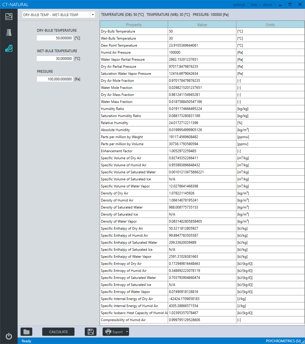
Psychrometrics Calculator allows the calculation of physical properties of humid air, water, steam, ice and psychrometrics commonly used in the design and operation of cooling towers.
Calculation of 42 properties of humid air, water, steam, ice and psychrometrics.
Allows for 17 combinations of two thermodynamic properties to be entered as input variables:
Dry-bulb Temperature / Wet-bulb Temperature
Dry-bulb Temperature / Dew Point Temperature
Dry-bulb Temperature / Relative Humidity
Dry-bulb Temperature / Humidity Ratio
Dry-bulb Temperature / Specific Enthalpy
Dry-bulb Temperature / Specific Volume
Wet-bulb Temperature / Dew Point Temperature
Wet-bulb Temperature / Relative Humidity
Wet-bulb Temperature / Humidity Ratio
Dew Point Temperature / Relative Humidity
Dew Point Temperature / Specific Enthalpy
Dew Point Temperature / Specific Volume
Relative Humidity / Humidity Ratio
Relative Humidity / Specific Enthalpy
Relative Humidity / Specific Volume
Humidity Ratio / Specific Enthalpy
Humidity Ratio / Specific Volume
Supports input parameters and calculation results in both SI (metric) and I-P (english) system of units.
For each combination of input thermodynamic variables, it calculates and provides the user with information about the appropriate values in the valid range of computations.
Calculation results can be saved to a to a database for later retrieval.
Calculation results can be exported to excel/pdf file formats.
Calculation of the properties of humid air, water, steam, ice and psychrometrics are based on the precision provided by the mathematical formulations of the following thermodynamic and transport properties models:
Properties of Water and Steam
Formulations from the IAPWS (International Association for the Properties of Water and Steam) IAPWS-IF97 Industrial formulation (Revision 2007) and related models.
Properties of Humid Air
Thermodynamic and psychrometric property algorithms from the ASHRAE Research Project 1485.
Scientific Formulation IAPWS-95, IAPWS Formulation 2008 and IAPWS Formulation 2006. Properties of dry air are from the NIST Reference equation of Lemmon et al.
Graphical User Interface
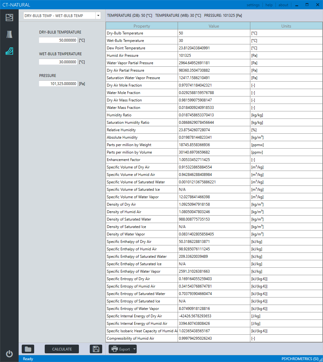
Range of Input Variables
| Property | Range in SI Units | SI Units |
|---|---|---|
| DRY-BULB TEMPERATURE | -143.15 ≤ Tdb ≤ 350.0 | °C |
| WET-BULB TEMPERATURE | -143.15 ≤ Twb ≤ 350.0 | °C |
| DEW POINT TEMPERATURE | -143.15 ≤ Tdp ≤ 350.0 | °C |
| RELATIVE HUMIDITY | 0 .0 ≤ RH ≤ 100.0 | [%] |
| HUMIDITY RATIO | 0.0 ≤ W ≤ 10.0 | kg/kg |
| SPECIFIC ENTHALPY | -311.357 ≤ h ≤ 32135.848 | kJ/kg |
| SPECIFIC VOLUME | 1.469E-3 ≤ v ≤ 3.055E5 | m3/kg |
| PRESSURE | 10.0 ≤ P ≤ 10.0E6 | Pa |
| Property | Range in I-P Units | I-P Units |
|---|---|---|
| DRY-BULB TEMPERATURE | -225.67 ≤ Tdb ≤ 662.0 | °F |
| WET-BULB TEMPERATURE | -225.67 ≤ Twb ≤ 662.0 | °F |
| DEW POINT TEMPERATURE | -225.67 ≤ Tdp ≤ 662.0 | °F |
| RELATIVE HUMIDITY | 0 .0 ≤ RH ≤ 100.0 | [%] |
| HUMIDITY RATIO | 0.0 ≤ W ≤ 10.0 | lb/lb |
| SPECIFIC ENTHALPY | -126.174 ≤ h ≤ 13823.61 | Btu/lb |
| SPECIFIC VOLUME | 2.353E-2 ≤ v ≤ 4.893E6 | ft3/lb |
| PRESSURE | 0.00145 ≤ P ≤ 1450.4 | psia |
Calculation Results
| Property | SI Units | I-P Units |
|---|---|---|
| Dry-Bub Temperature | °C | °F |
| Wet-Bulb Temperature | °C | °F |
| Dew Point Temperature | °C | °F |
| Humid Air Pressure | Pa, kPa, bar, mmHg | psia, inHg, inH2O, atm |
| Water Vapor Partial Pressure | Pa, kPa, bar, mmHg | psia, inHg, inH2O, atm |
| Dry Air Partial Pressure | Pa, kPa, bar, mmHg | psia, inHg, inH2O, atm |
| Saturation Water Vapor Pressure | Pa, kPa, bar, mmHg | psia, inHg, inH2O, atm |
| Dry Air Mole Fraction | [-] | [-] |
| Water Mole Fraction | [-] | [-] |
| Dry Air Mass Fraction | [-] | [-] |
| Water Mass Fraction | [-] | [-] |
| Humidity Ratio | kg(w)/kg(da), g(w)/kg(da) | lb(w)/lb(da), gr(w)/lb(da) |
| Saturation Humidity Ratio | kg(w)/kg(da), g(w)/kg(da) | lb(w)/lb(da), gr(w)/lb(da) |
| Relative Humidity | [%] | [%] |
| Absolute Humidity | kg(w)/m3 | lb(w)/ft3 |
| Parts per million by weight | ppmw | ppmw |
| Parts per million by volume | ppmv | ppmv |
| Enhancement Factor | [-] | [-] |
| Specific Volume of Dry Air | m3/kg, cm3/g | ft3/lb, in3/lb |
| Specific Volume of Humid Air | m3/kg, cm3/g | ft3/lb, in3/lb |
| Specific Volume of Saturated Water | m3/kg, cm3/g | ft3/lb, in3/lb |
| Specific Volume of Saturated Ice | m3/kg, cm3/g | ft3/lb, in3/lb |
| Specific Volume of Water Vapor | m3/kg, cm3/g | ft3/lb, in3/lb |
| Density of Dry Air | kg/m3, g/cm3 | lb/ft3, lb/in3 |
| Density of Humid Air | kg/m3, g/cm3 | lb/ft3, lb/in3 |
| Density of Saturated Water | kg/m3, g/cm3 | lb/ft3, lb/in3 |
| Density of Saturated Ice | kg/m3, g/cm3 | lb/ft3, lb/in3 |
| Density of Water Vapor | kg/m3, g/cm3 | lb/ft3, lb/in3 |
| Specific Enthalpy of Dry Air | J/kg, kJ/kg | Btu/lb, ft lbf/lb |
| Specific Enthalpy of Humid Air | J/kg, kJ/kg | Btu/lb, ft lbf/lb |
| Specific Enthalpy of Saturated Water | J/kg, kJ/kg | Btu/lb, ft lbf/lb |
| Specific Enthalpy of Saturated Ice | J/kg, kJ/kg | Btu/lb, ft lbf/lb |
| Specific Enthalpy of Water Vapor | J/kg, kJ/kg | Btu/lb, ft lbf/lb |
| Specific Entropy of Dry Air | J/(kg·K), kJ/(kg·K) | Btu/(lb·°R), ft lbf/ (lb·°R) |
| Specific Entropy of Humid Air | J/(kg·K), kJ/(kg·K) | Btu/(lb·°R), ft lbf/ (lb·°R) |
| Specific Entropy of Saturated Water | J/(kg·K), kJ/(kg·K) | Btu/(lb·°R), ft lbf/ (lb·°R) |
| Specific Entropy of Saturated Ice | J/(kg·K), kJ/(kg·K) | Btu/(lb·°R), ft lbf/ (lb·°R) |
| Specific Entropy of Water Vapor | J/(kg·K), kJ/(kg·K) | Btu/(lb·°R), ft lbf/ (lb·°R) |
| Specific Internal Energy of Dry Air | J/kg, kJ/kg | Btu/lb, ft lbf/lb |
| Specific Internal Energy of Humid Air | J/kg, kJ/kg | Btu/lb, ft lbf/lb |
| Specific Isobaric Heat Capacity of Humid Air | kJ/(kg·K) | Btu/(lb·°R) |
| Compressibility of Humid Air | [-] | [-] |
CT-Natural - Natural Draft Counterflow
Graphical User Interface
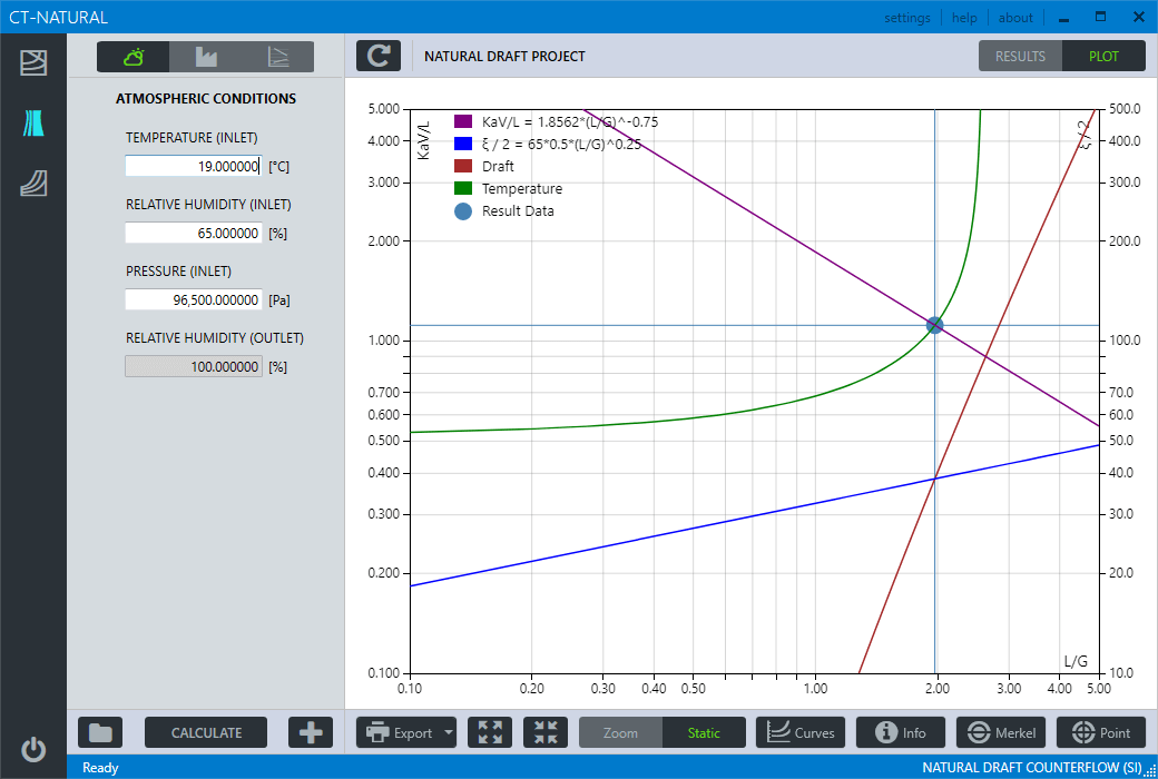
CT-Natural - Natural Draft Counterflow
Numerical results in calculation project
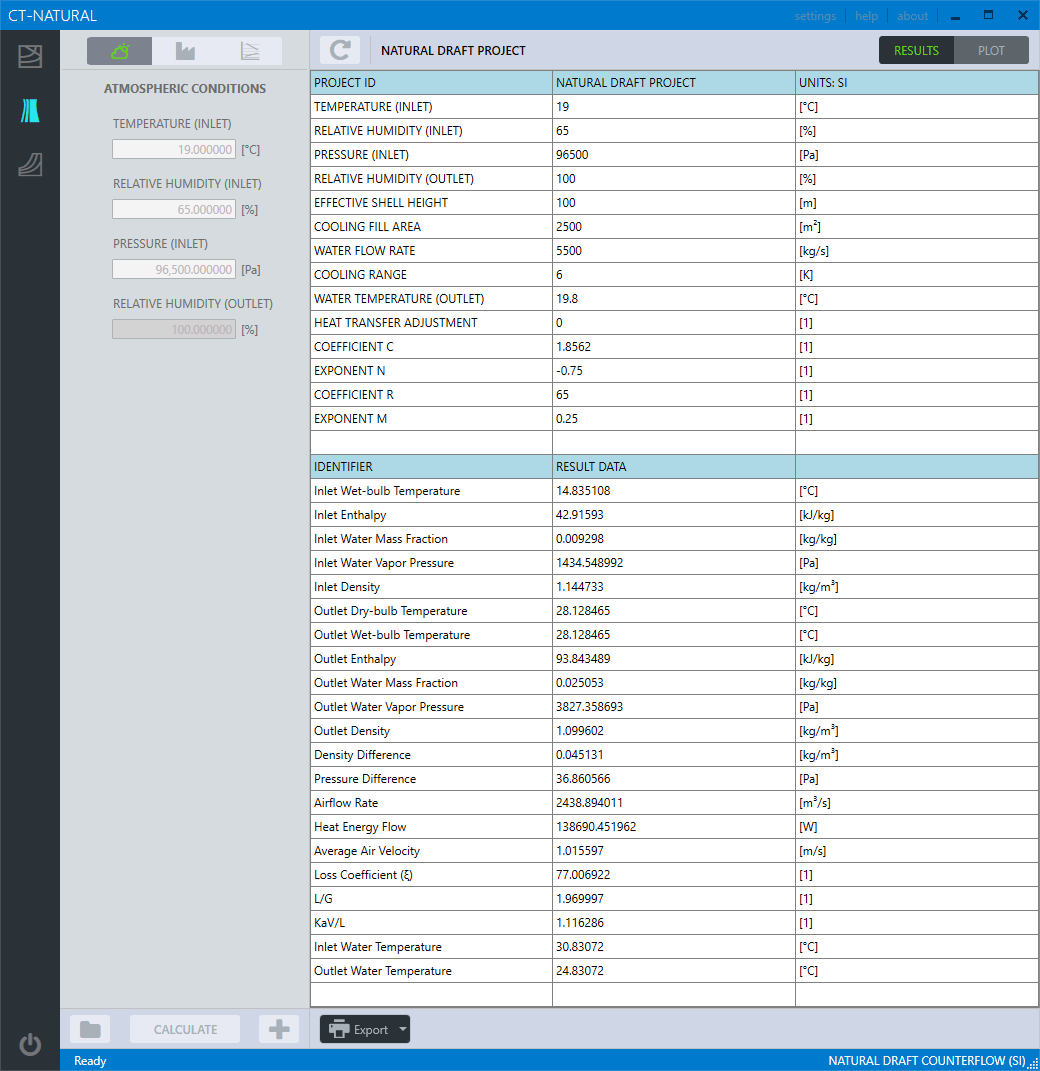
CT-Natural - Natural Draft Counterflow
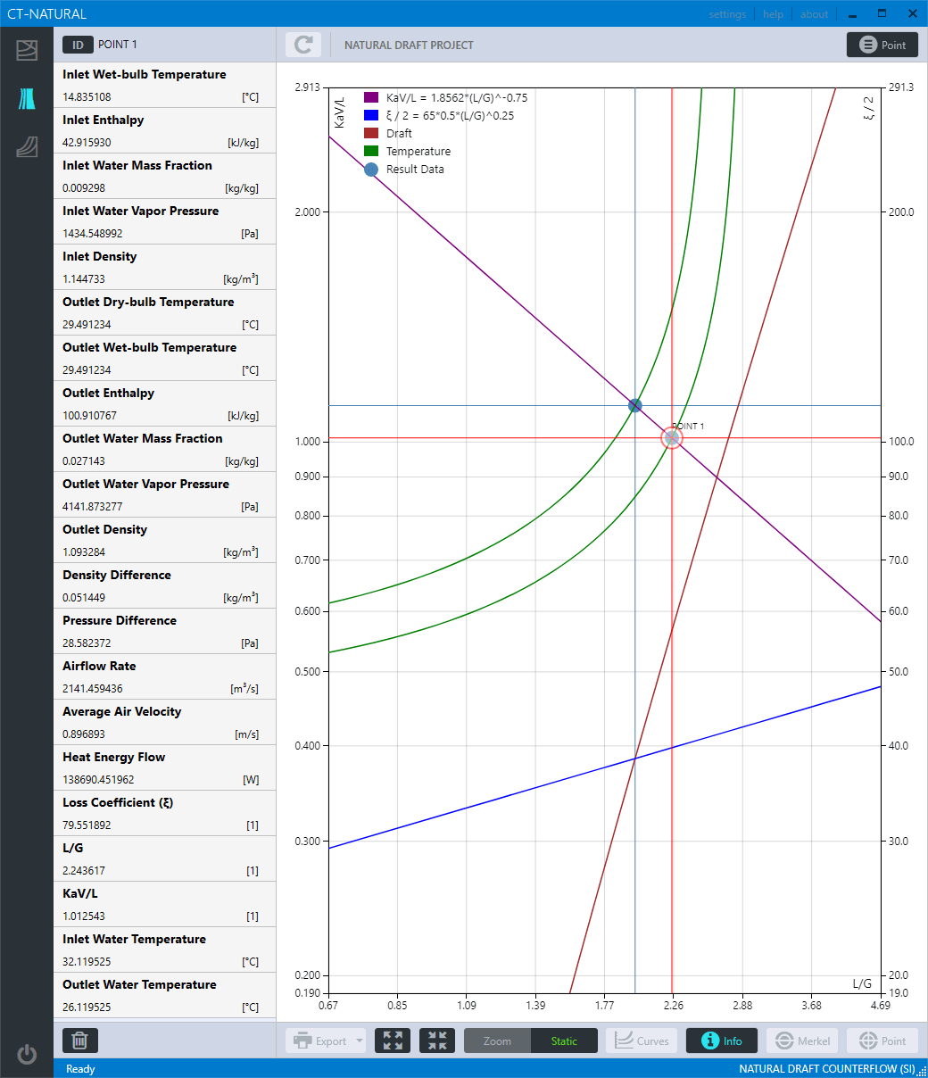
Numerical results from data point
CT-Natural - Demand Curves
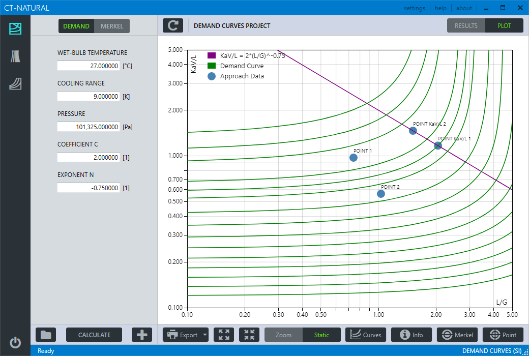
Graphical User Interface
CT-Natural - Demand Curves
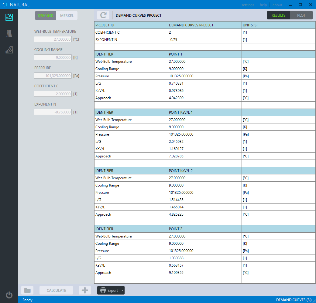
Numerical results in calculation project
CT-Natural - Demand Curves
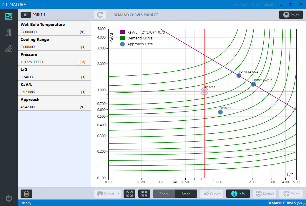
Numerical results from approach data point
CT-Natural - MErkel Number
MErkel number calculation result
CT-Natural - Psychrometrics
Graphical User Interface